86-519-69815927
East Liutang Village, Hengshanqiao Town, Wujin District, Changzhou, Jiangsu, China (Mainland)


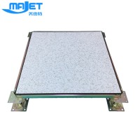
High quality bare finish cabling raised floor with long-term service, US $ 18 - 21 / Square Meter, Jiangsu, China, BASIC, FS800-FS2000.Source from Changzhou Basic Computer Room Equipment Co., Ltd. on Waimaotong.com.
| Material | Steel |
| Color | Grey |
| Usage | Modern office |
| Size | 600x600mm |
| Thickness | 34mm |
| Application | Offices |
| Certification | ISO9001 |
| Product Keywords | bare finish raised floor for cabling |
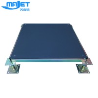
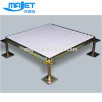
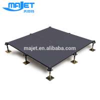
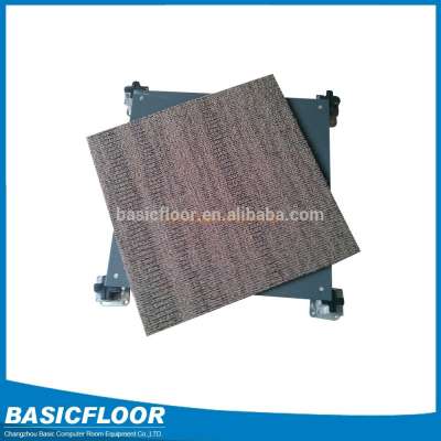
OA raised access floor
Description:
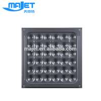
Full steel, independent for corners support structure. Lower plate is ST14 stretched plate, surface is SPCC hard steel painted with conductive anti-static resin, foaming cement in filled, lock hole in four corners. Pedestal is pressured forming with galvanized or cast aluminum, lead screw can be adjusted at discretion.
Feature:
1. Whole steel combination framework with strong intension and shockproof ability
2. High size precision and good interchangeability
3.Fireproofing, waterproof and dustproof
4.The four sides are fixed very well to avoid moving of floor with good walking feel.
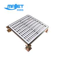
5.The mould of outlet interface is molding; it is easy to wiring and the installation of earth socket is more convenient.
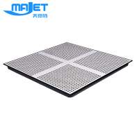
6.The nether part can be used as airiness for air-conditioning.
7.For the overweight equipment, it can solve the overload problem only with adding bracket under the floor.
8.Convenient dismounting and it can be repeated used.
Installation:
Field area
STEP 1. Clean up the room for installation. Making sure there is no sand , grease, oil or any wax on the ground. Any hole will be filled to level. Elevation deviation at sub-floor shall not exceed 10 mm (3/8 inches) within one meter (3 feet).
Check the room dimensions and configuration against approved drawings. Using a laser, shoot in the areas to receive access floor to determine how much variation there is in the level of the subfloor within the room and at the termination points, such as elevator and door sills and concrete ledges.
STEP 2. Find the starting point in the room as shown on the drawings. Seek approval to change the starting point if cut panels at the perimeter will be too small to allow proper support. Recommended minimum size of the cut panels for proper support is 6 inches wide.
STEP 3. Having established the proper starting point, lay out two chalk lines at right angles to make sure the room is square. Chalk lines must be used as control lines for installing the access floor. The chalk line system gives a square reference point. Be careful to keep the access floor square at all times during installation.
STEP 4. Chalk the two control lines and spread pedestal assemblies in an area approximately 48 feet x 24 feet, making sure to start at the approved starting point.
STEP 5. Using a laser shoot in a pedestal assembly to the proper FFH every 8 or 10 feet in both directions. By spanning two pedestals at proper FFH with the leveling bar, adjust all the pedestals in between to the bottom surface of the bar. As you adjust each pedestal assembly, center it on the two-foot marks permanently marked on the bar.
STEP 6. Glue each pedestal base in the spread area to the subfloor. Using a spatula type device, tilt up base plate without changing its location and apply adhesive to bottom of base plate. T.
STEP 7. If stringers are a part of the system, bolt them to the pedestal heads beginning at the starting point
STEP 8. Beginning again at the start point, lay four rows of panels along the longest wall. Check to see that you are staying on control lines, and that panels do not rock.
STEP 9. If a panel rocks diagonally when placed in the system, turn it one quarter (90°) turn and check it again. If the panel continues to rock when rotated, some debris may be between the panel bottom and the pedestal head or stringer. Also check to make sure pedestal is not tilted, stringers are properly seated and that panel edges are flush. If the panel still rocks, set it aside to be used as perimeter cut panel. The pedestals should not be adjusted unless three or four panels supported on it are rocking. At this point, make a minor elevation adjustment to the pedestal.
STEP 10. After laying the first four rows of panels along the long wall, begin again at the starting point and lay four rows of panels perpendicular to the first rows. Follow the same previous steps (8 through 9) for laying panels and be sure to follow the control lines. If you do not stay on the control lines, the floor will not be square and your grid lines will not be straight. While you are laying panels in this area, you should have someone spreading, shooting, leveling and preparing the next adjacent area for panels.
STEP 11. After the first section of a floor is installed, check to see that all the grid lines are straight. If the grid is not square, you can make them square by bumping the rows of installed panel with your foot. If this fails, take up every third or fourth row of panels and tap the bases in the direction of the panels that have to be moved. All grid lines should be straight before cutting in the perimeter panels.
NOTE: If rolling materials, equipment or gang boxes across installed access floor,
then 1/2-inch plywood should be used as pathways to avoid any damage to the top surface of the access floor panels.
CUT IN procedure
Cut in the access floor to perimeter wall, curbs and around columns after the main field areas are installed. It may be necessary at times to install some cut panels in order to hold the floor tight and align the grid, or to laterally stabilize the system. All cut panels are measured and precisely cut to fit in their own place, and are usually not interchangeable with other cut panels. Cut panels should fit snug. Make sure the perimeter pedestals are close to the wall, plump, and at correct height.
NOTE: The most efficient equipment for cutting perimeter panels is a portable band saw with bi-metal, 14-tooth, 1/2-inch wide x .034-inch thick blades.
NOTE: Consider the use of protective personal equipment normally recommended in machine shop practice:
a.Safety Glasses
b.Comfortable leather or cotton-face gloves.
FASCIA ASSEMBLY
STEP 1. To locate the position of the bottom angle, plumb down from the edge of the A/F to the subfloor with a level. Mark the subfloor.
STEP 2. Notch the bottom angle around pedestal bases and secure the bottom angle to the subfloor by using adhesive and powder-actuated fasteners.
STEP 3. Place the fascia plate with ribbed side out against the bottom angle and the edge of the access floor panel. If the fascia is above the floor, mark it at the floor height by scribing along the top of the floor. Cut the fascia about one-eighth inch smaller than the mark. When you have the fascia cut, start to secure it to the bottom angle with pop rivets. If more than one piece of plate is used in line, be sure the ends butt together and leave no gap.
STEP 4. Fasten the trim angle on the top edge. Mitre the nosing at all corners. Drill and countersink all the holes in the angle, keeping them equally spaced on 18-inch centers. Attach the angle to the surface of the floor panel with flathead sheet-metal screws.
STEP 5. Access floor panels need to be laterally stable. This can be accomplished by: running stringers perpendicular to fascia; fastening panel to understructure; using diagonal bracing.
Ramps
STEP 1. Locate the ramp shoe where it belongs. Drill and countersink two 1/4-inch diameter holes every 24 inches equally spaced starting 6 inches from the end of the ramp shoe. A two-piece shoe is to be riveted together as shown in section A-A Figure
6.After drilling and countersinking the ramp shoe, recheck its location, and use a hammer drill with a ¼ inch masonry bit to drill 2 ½-inch-deep holes into the concrete. Place ¼-inch x 2-inch-long flat-head drive rivets in the holes and drive them flush with the surface of the ramp shoe.
STEP 2. Cut and install all access floor panels adjacent to the ramp well.
STEP 3. Install handrail, if applicable.
STEP 4. Install fascia assembly on either side of ramp that butts the access floor. STEP 5. Place the ramp stringers (recut slope as needed) and the pedestal supports in their appropriate places within the ramp well. Ramp stringers must be at both sides of the ramp and located on two-foot centers.
STEP 6. Place the 2 X 3/16-inch steel flat bar cross braces on two-foot centers starting from ramp shoe. Secure flat bars to ramp stringers with pedestal adhesive and ¼"-20 flat-head sheet-metal screws, one per intersection of bar and stringer.
STEP 7. Place all full and cut panels on ramp.
PREFORMED STEEL STAIRS
STEP 1. Lay out and cut floor panels adjacent to the step well, giving you the proper well opening for your step.
STEP 2. Install handrail, if applicable.
STEP 3. Install fascia assembly on either side of step that butts the access floor. STEP 4. Secure a steel bottom angle to the floor and on the inside of the bottom riser of your preformed step; this will be used to fasten the step in place. Secure bottom angle by glueing to the subfloor with pedestal adhesive and by shooting down with powder-actuated fasteners on 24-inch center.
STEP 5. Place the step in proper position. The steel bottom angle should be inside. Fasten the step to the bottom angle with pop rivets.
STEP 6. Cover the risers with aluminum fascia plate using pop rivets. STEP 7. Laminate the treads with selected covering.
STEP 8. Attach aluminum top trim angle to the edge of each tread and around the step well at the edge of the access floor. The trim angle is attached with flat-head sheet-metal screws (no rivets). Holes are to be spaced on 18-inch centers and countersunk.
Our Services:
Whether you choose us or not finally,any questions about the raised floor systems you can feel free to ask us.We will take all our customers as our best friends ,so the best services will be provided at any time.
Company Information:
Changzhou Basic Computer Room Equipment.,Ltd is a new company ,but we have professional workers and sales team,not worse than other suppliers .What we can do is to improve our productss quality and services. Welcome to send us inquiries !

The steel cementitious bare finish access floors are packed by wooden pallet.
5-25 days after confirming order,detail delivery date should be decided according to
production season and order quantity.